Making Real Things
My family makes exchanging hand-made gifts a yearly Christmas tradition. These gifts can be anything from candied nuts to braided keychains. For me, the making process typically starts a few months prior. I take a simple idea, like coasters, ornaments, stamps, or boxes, then over the next few weeks receive my annual lesson on the effort and frustration that goes into creating physical-world items as opposed to software. To keep my spirits up I’ll first describe the finished product before recounting the construction experience.
Look Mom, A Box!
Here are some pictures of a finished box. This one is walnut and like all the boxes finished in a few coats of tung oil.
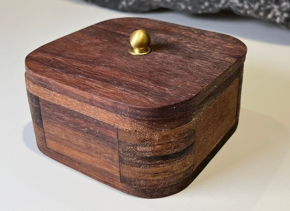
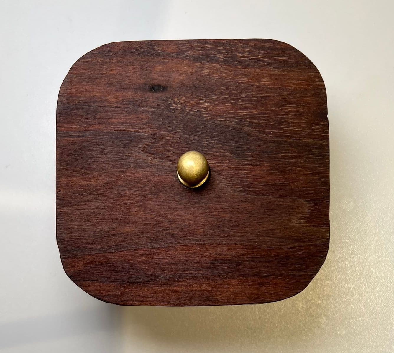
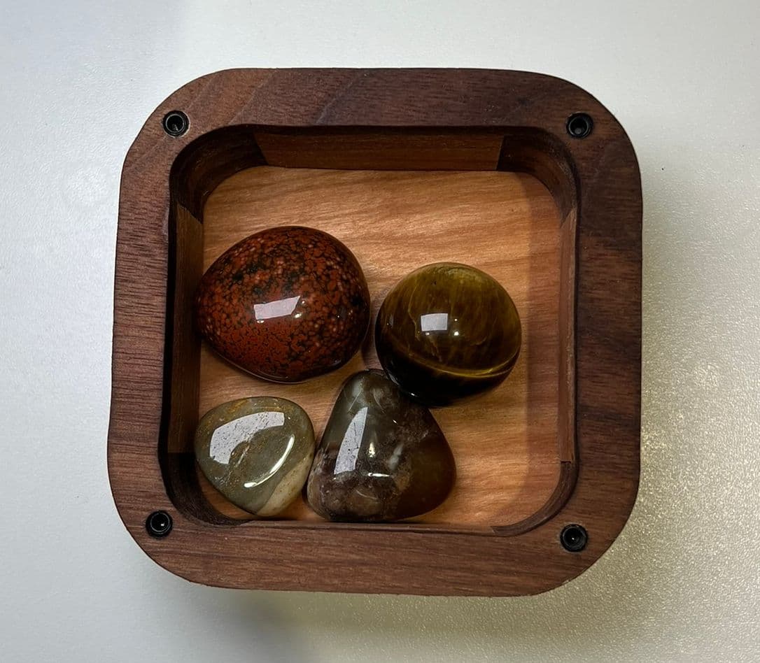
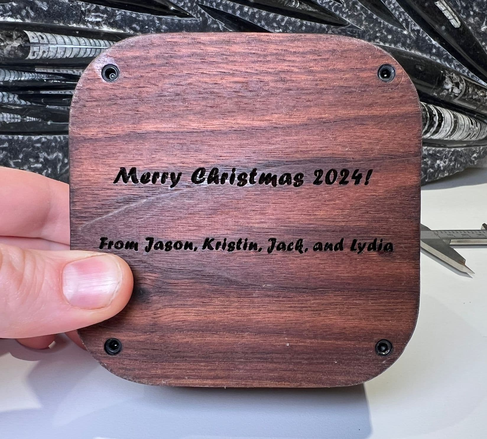
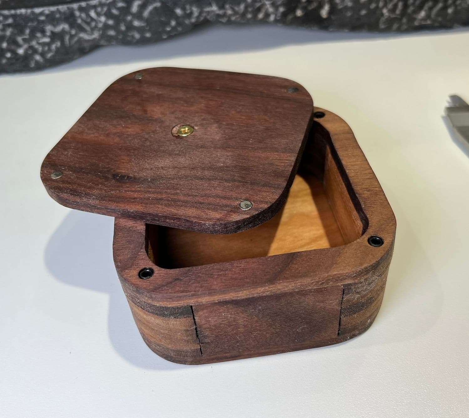


It’s a bit rustic, but I’m pleased with the results. Now to relive the process 😅.
Equipment Background
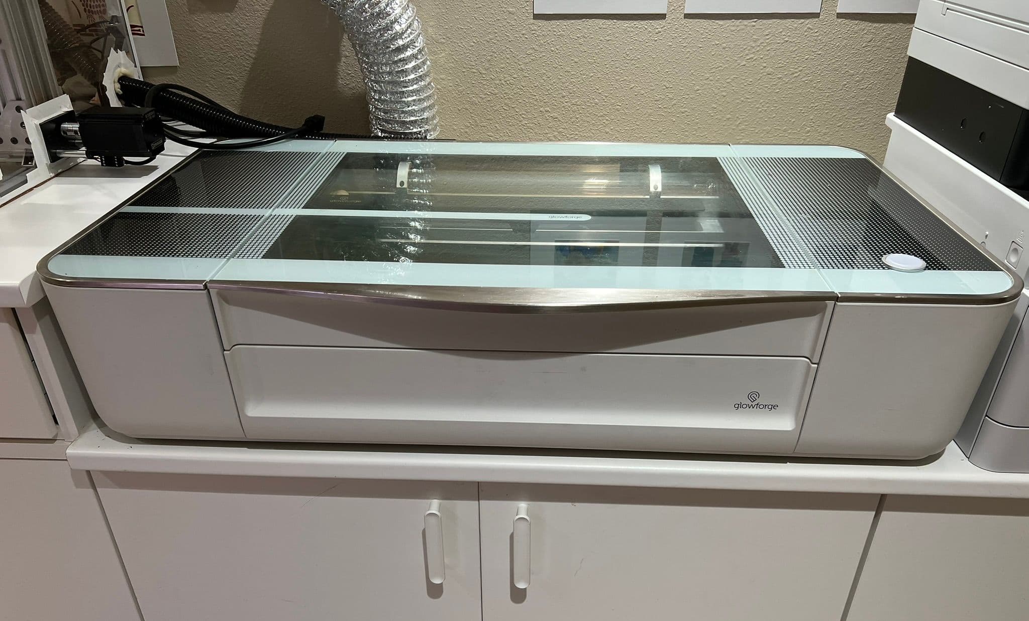
In 2020 I acquired a Glowforge Basic which has been my workhorse of hand-made gifts. However, laser-cut projects have a characteristic “charred edge” look and my previous gifts were mostly two-dimensional. With the project this year, I wanted to break out of that pattern and deliver something nobody could tell was laser-cut.
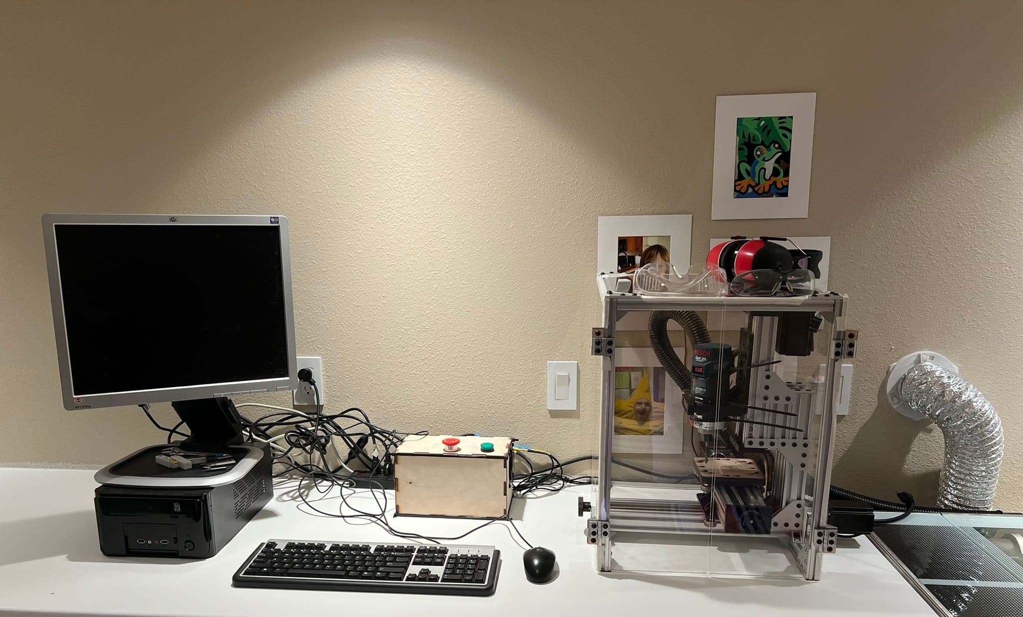
To that end, I decided to rehabilitate some other equipment I’d used much earlier. In 2012, I put together a Fireball v90 CNC router, which I controlled with LinuxCNC. I made a few projects at the time, culminating in a wooden model of Mount Rainier carved from height-map data. However I really hated the dust in my garage from every project, and in 2017 I moved to a new house where the router didn’t quite fit anywhere. I ended up disassembling it for parts. In 2019 I bought an OpenBuilds MiniMill frame with the intent of re-using the old electronics, but then I switched jobs, became busy, and never finished assembling it.
So, for this project, I planned to finish the MiniMill and use it to modify laser-cut pieces in ways the laser could not, including cleaning up the charred edges by routing around the outside and inside of the boxes, thus hiding all evidence of the laser cutter. To take care of the dust, I would enclose the entire device in acrylic under negative pressure, vented through a shop-vac to the outside through a clothes dryer port I had already installed for the Glowforge exhaust.
Design
Constraints
My plan to route-around the outside of the boxes using the MiniMill provided the main constraint on the box size - the MiniMill can only travel 4.5”/120mm on the X Axis and 3”/80mm on the Z Axis, limiting a square box to ~4”/~100mm by ~2.5”/~60mm. Beyond the size, constraints came from the need to design for assembly and my lack of tools beyond the Glowforge and MiniMill.
Overall Style
I wanted a box with a rounded look that would help distinguish it from a typical box from MakerCase. At first I planned to form the box by stacking a bunch of flat loops, sort of like those wooden interlocking train tracks stacked on top of each other. This would allow me to achieve a rounded profile impossible for a typical laser-cut finger-joint box.
However, after I purchased a bunch of wood, I realized that stacked edges weren’t nearly as nice looking as the face. Wood looks better in large, flat panels where the flowing patterns have space to reveal themselves. I decided that the sides of the box would be flat panels that would slot in to stacked rounded corners. That way I could have both a rounded profile and show off the best of the wood.


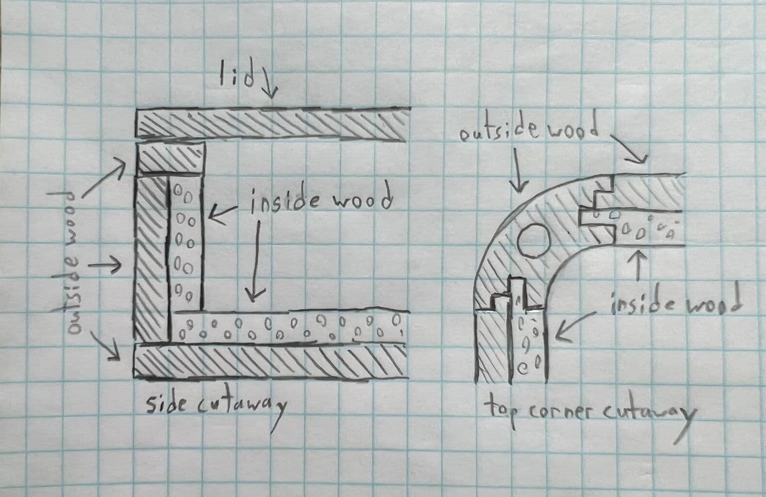
I decided the boxes would have an outer component and an inner component. This “double-hull” approach had a bunch of advantages:
- The outside and inside could be different types of wood.
- The thickness and multiple pieces would help prevent visible gaps/holes.
- A thicker multi-piece side is less vulnerable to warping.
- The double thickness looked proportionate to the box dimensions.
Here’s a sketch of how the box is formed from outside and inside pieces, and how the edge pieces meet at the rounded corners.
Mount Points
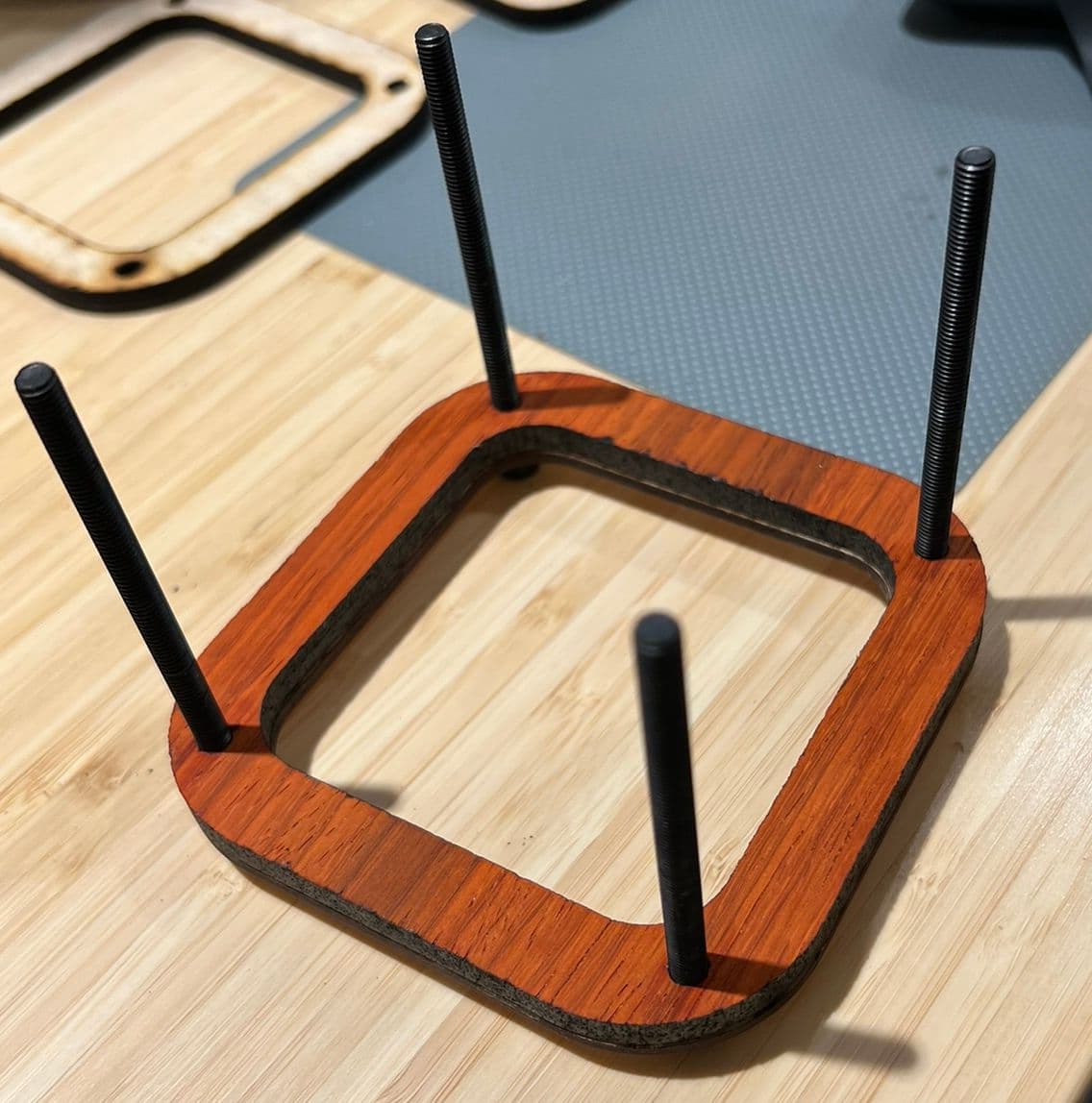
Unlike with the gentle burning of the Glowforge, in the MiniMill the box needed to be securely held down. For past projects I’d used double-sided carpet tape, and it worked really well, but I was concerned that with the small size of the boxes the tape would not be secure enough to withstand the forces of the router. I decided to put holes through each corner of the box, so that the box could simply be bolted to the platform in the MiniMill. These holes could also be used to clamp the box together during gluing and later used for the magnetic lid attachment.
Lid
I considered lid mechanisms with barrel hinges, locking sliders, tabs, and slots, but none seemed feasible with my equipment. I settled on a simple approach: the lid would contain small round magnets embedded in a pocket, which would attract ferrous grub screws inserted into the mounting holes. I built a model of this and it seemed to work nicely. Based on my wife’s feedback, I added a brass knob to the top of the lid to add some color and to allow the lid to be easily lifted.

Plans
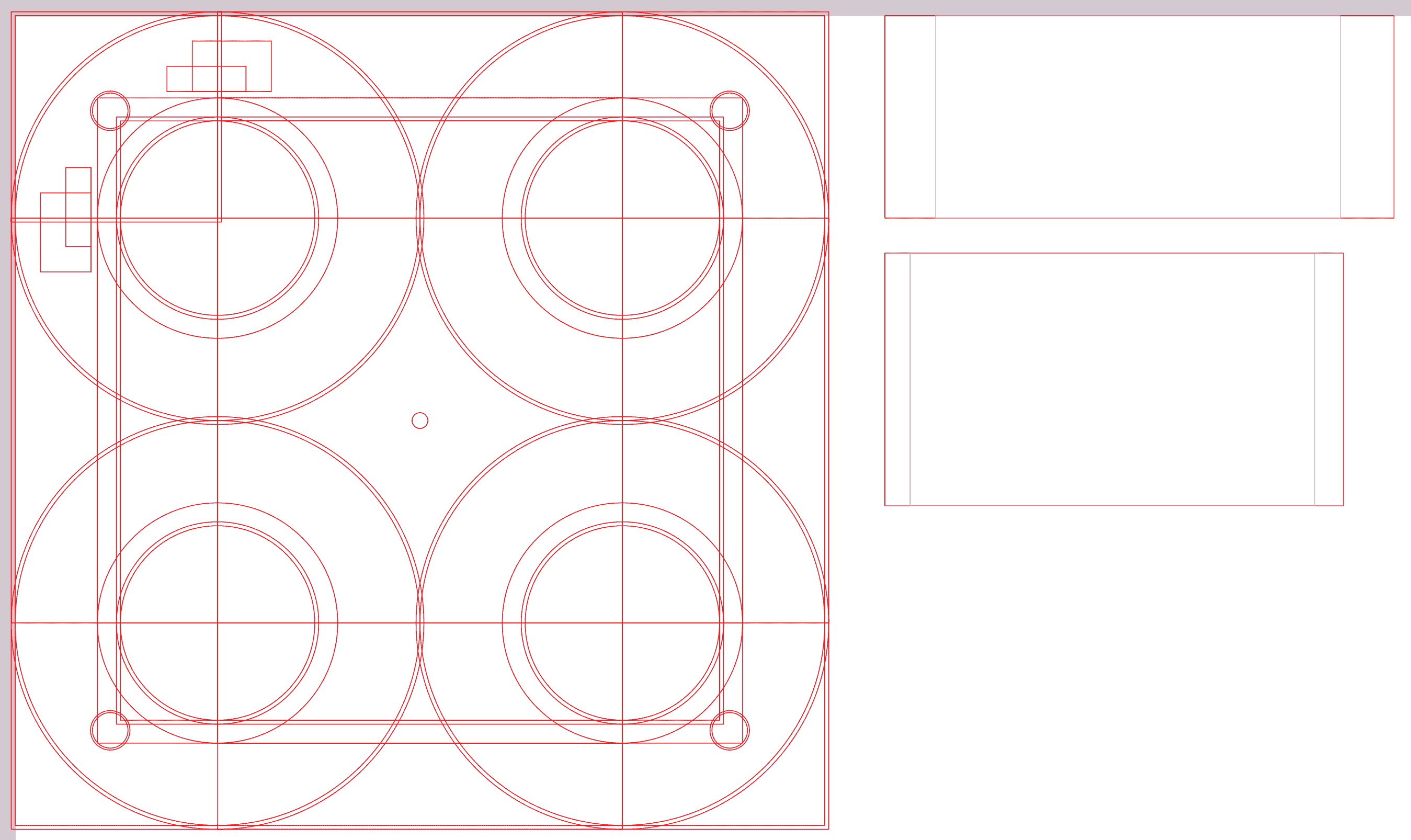
First I created a design file with all the pieces in Inkscape made out of primitive shapes combined with boolean geometry operations. I’m pretty sure OpenSCAD’s script-based approach would have been a nicer experience, but so far I have not attempted to use that program to generate files for the laser cutter. Maybe next time! Here’s the main template that has all the pieces on it at once.
From this main file I created separate files for each piece I needed to cut out.
Execution
Cutting the Pieces
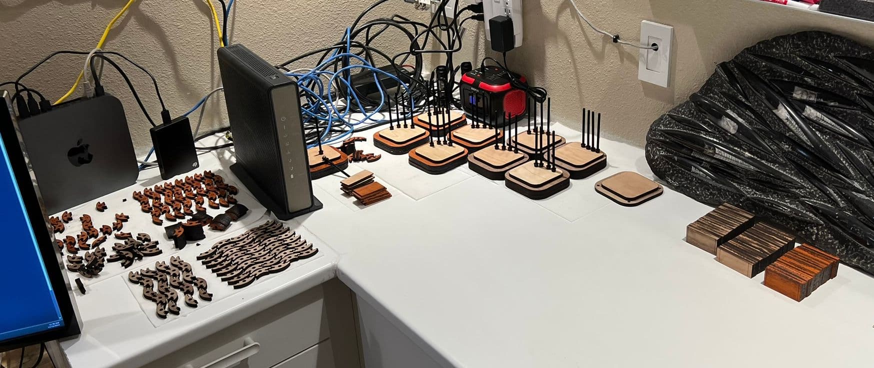
Each box comprises 1 lid, 1 top, 4 outer sides, 4 inner sides, 16 side corners, 4 bottom corners, 1 inner bottom, and 1 outer bottom, for a total of 32 pieces. The pieces were ~6.4mm thick so required three passes for a clean through-cut from the Glowforge. To make 9 boxes I think it took maybe 6 hours of laser-cutting, but I spread it across a few days so I’m not totally sure.
One key thing to note: typically when laying out pieces to cut I will rotate them to pack as many as I can onto the stock. However, with this project I realized it was critical to take the grain direction into account. I cut a large number of outer sides with the grain going vertically instead of horizontally, and had to re-cut them. I also didn’t notice I missed cutting half of the inner sides until assembly.
Notching the Side Pieces
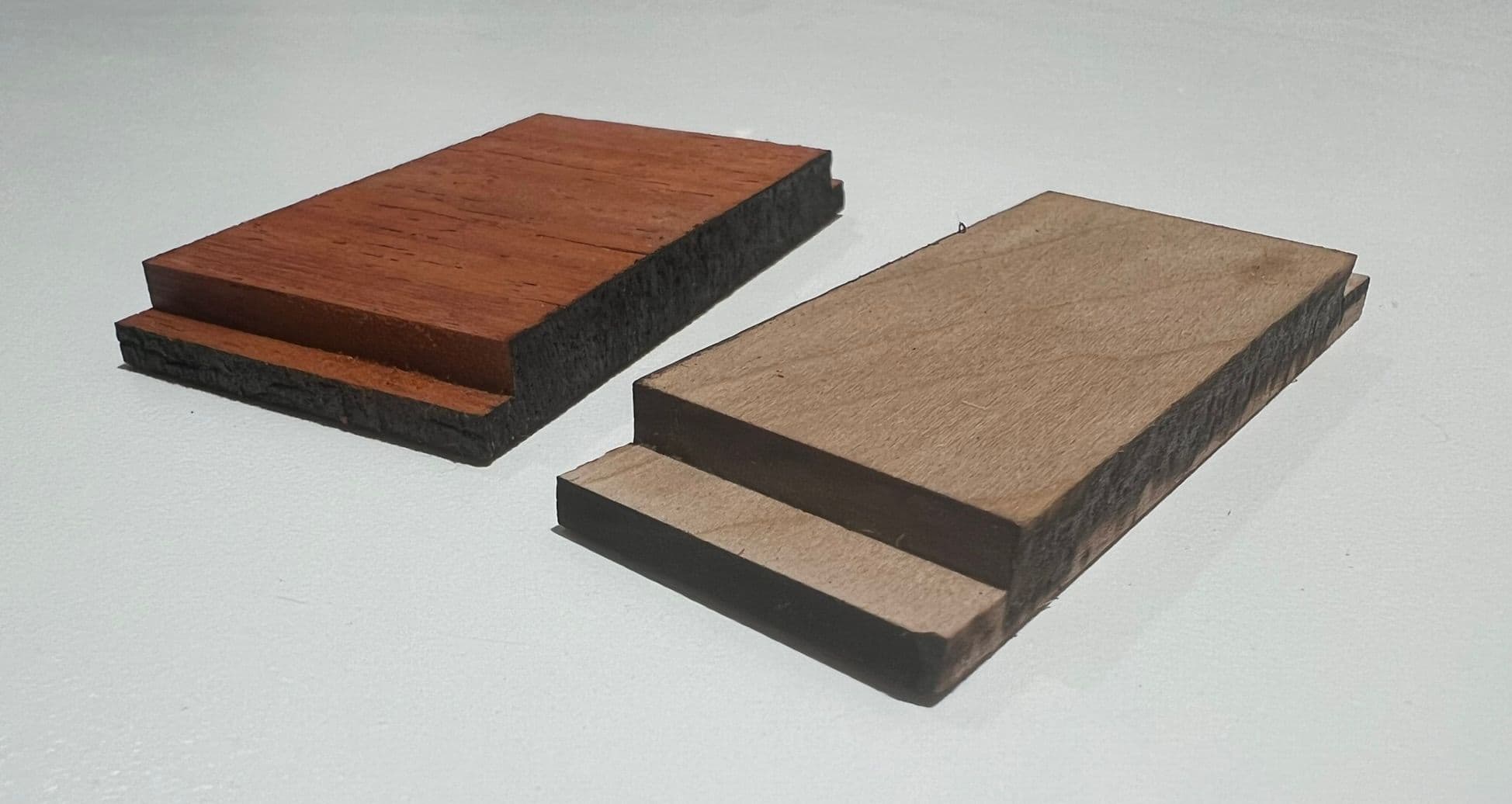
To fit snugly into the slots in the corners, the sides needed to be notched. I did this in the MiniMill by holding the end of each piece against a fence and manually jogging the router across it. This made quick work of the notches. Unfortunately, this particular motion did not uncover a problem with my router setup that led to some major issues later when routing out the inside of the boxes. I first tried using an upcut spiral bit for the notches but that left a rough edge, so I switched to a downcut spiral bit which kept things very smooth.
First Gluing
At this point I was way behind schedule and working late at night, and I did not take any pictures or video of the actual gluing. So, you will have to work with a description of the process.
For glue, I used TiteBond Speed Set. The main selling point of this glue for me was the “gap filling properties” which I felt could compensate for any cut errors.
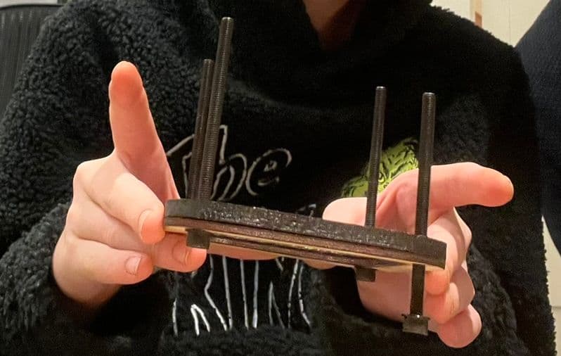
For the first stage of gluing, I took the top and put some bolts through it - you saw this in the mount points picture above. Then, I stacked on all the corner pieces over the bolts, adding glue as I went. Once that was done, I pushed a layer of plastic wrap over the assembly, and added the inner and outer bottom to the stack. I then tightened nuts over each bolt to clamp everything together.
Gluing first without attaching the bottom meant there would be room for the router bit to move around the inside without scarring the inner bottom. It also meant that all sides and corners would be glued flush against the top, and any height variation would manifest itself when adding the bottom later. With a two-layer bottom, no gap could provide a visible hole all the way into the box, so it was better for a gap to manifest there than against the top.
A Minor Problem
While gluing I noticed a problem: on the walnut boxes, the corners were about a millimeter taller than the sides. This should not have been possible, since after cutting the corner pieces, I had stacked them and measured the stack thickness using calipers, and used that measurement for the sides. Unfortunately for me, I only measured the padauk corner thickness, and assumed the same applied to the walnut. As it turned out, each walnut board was almost 0.2mm thicker than the padauk, an error that accumulated to make the walnut corners a full millimeter taller. This seems like a small amount, but it formed an ugly gap with the bottom.
I could correct the gap by shaving the walnut corners down to the designed height. The height of the corners needed to be corrected at two levels - an inside shelf at layer four that the inner bottom rested on, and the full stack the outer bottom rested on.
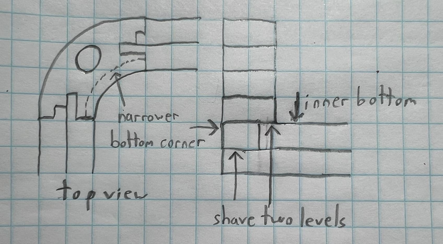
The inside shelf was difficult because it was a quarter-circle, a challenging path to follow by hand. I decided to use G-code for a circular arc. G-code is a language for controlling automated tools and LinuxCNC interprets it to command movement of the router. I used a script similar to the one here to make the tool follow the quarter-circle with the correct radius. You can see the effects of this program at ncviewer.com.
G21 (millimeter mode)
G1 X0 Y0 (move to 0,0)
G2 X10 Y10 I10 J0 (arc to 10,10 around origin at 10,0)
For each inside corner, I pushed a box against a fence and ran the program. After the first few cuts, the router started cutting a little into the bottom corner piece. This should not have been possible because the fence constrained the box position in that direction. I attributed it to some manual error since I was typing all the commands by hand. This mistake did not matter as it just made the pocket for the inner bottom a bit wider than necessary in the corners, not visible at all once the box was assembled. Little did I know that this was the first manifestation of a serious issue with my machine, and I should have stopped here and investigated!
Inside Routing
Once the glue had dried it was time to clean up the inside of the boxes with the router. I wrote a Python program to generate the G-code. Here the program is designed to trace the inside of the box, minus an “offset” in millimeters of the amount to shave.
side_length = 75.8
corner_radius = 12.3
offset = 1.5
tool_radius = 6.35 / 2  # 9.525 is 3/8; 6.35 is 1/4"
adjustment = offset - tool_radius

H = (side_length / 2) + adjustment
S = H - (corner_radius) - adjustment
R = corner_radius + adjustment

print(f"G21")
print(f"F100")
print(f"G90")
print(f"G0 X0.000 Y0.000")
print(f"G1 X{-H:.4f} Y{S:.4f}")
print(f"G2 X{-S:.4f} Y{H:.4f} I{R:.4f} J0.0000")
print(f"G1 X{S:.4f} Y{H:.4f}")
print(f"G2 X{H:.4f} Y{S:.4f} I0.0000 J{-R:.4f}")
print(f"G1 X{H:.4f} Y{-S:.4f}")
print(f"G2 X{S:.4f} Y{-H:.4f} I{-R:.4f} J0.0000")
print(f"G1 X{-S:.4f} Y{-H:.4f}")
print(f"G2 X{-H:.4f} Y{-S:.4f} I0.0000 J{R:.4f}")
print(f"G1 X{-H:.4f} Y{S:.4f}")
print(f"G0 X0.0000 Y0.0000")
print(f"M30")
The program starts with the router bit at position 0,0 relative to the box. I laser-cut a jig that allowed me to align the bit with the box at this position. I then started with offset zero and progressively increased it until it shaved the right amount. Here’s a short clip of the process.
Unfortunately this is where the issue with my machine finally caused a visible flaw.
A Major Problem
You might have noticed from the pictures of the finished box that one side was thicker than another. This reflects a problem I encountered while routing the inside of the boxes. As the router traveled around the box, on the third side it shaved slightly less, and on the fourth side it shaved none at all. And, I did not notice until the third box or so that the zero position of the machine was “drifting” with each box. Just like before with the manual shaving, for a few boxes I started cutting too much, but this time the error was visible!
I decided that my MiniMill was suffering from “backlash”. This is a mechanical problem where on a direction change, there is a “dead zone” and some steps are lost, leading to an accumulation of error over time. I later learned that this was a completely incorrect diagnosis. However, for the interiors of the boxes I struggled through it by manually zeroing the machine on each run, and adding a “backlash compensation” component to the python script. Fortunately the error mostly led to cutting too little, not too much, so a major flaw of uneven side thickness only became apparent on a few of the boxes.
The lack of precision also troubled me because the router bit was getting very close to the heads of the hold-down bolts. If they made contact, the box or the router bit would probably explode. So I cut the heads off of the bolts to ensure more clearance.
Another Minor Problem
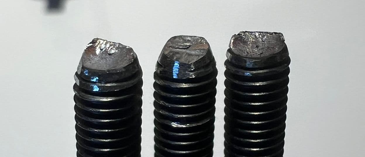
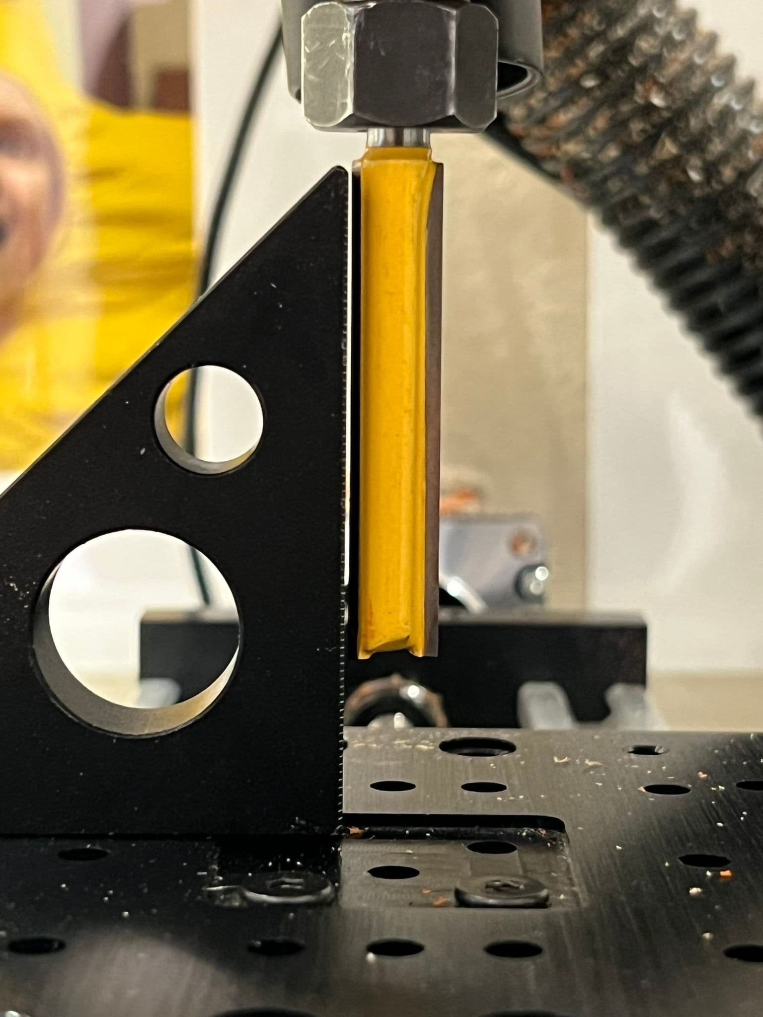
I faced another issue with the router bit. I had purchased a two-pack of very long straight-edge bits from Amazon for $15. For those who have purchased router bits, you will recognize this as an almost impossibly low price. But they certainly looked like router bits. What could go wrong?
The answer is that whatever the bits were made of, they were not sharp enough. On a few of the boxes, they ripped some big chunks out of the corner pieces. It wasn’t too noticeable, but I started worrying about the outside of the box where it would matter more.
A Positive Note
The dust/chip collection worked perfectly. While running, the doors of the enclosure were noticeably sucked inward, and after all the cutting my workshop, which is also my office, remained perfectly clean!
Second Gluing
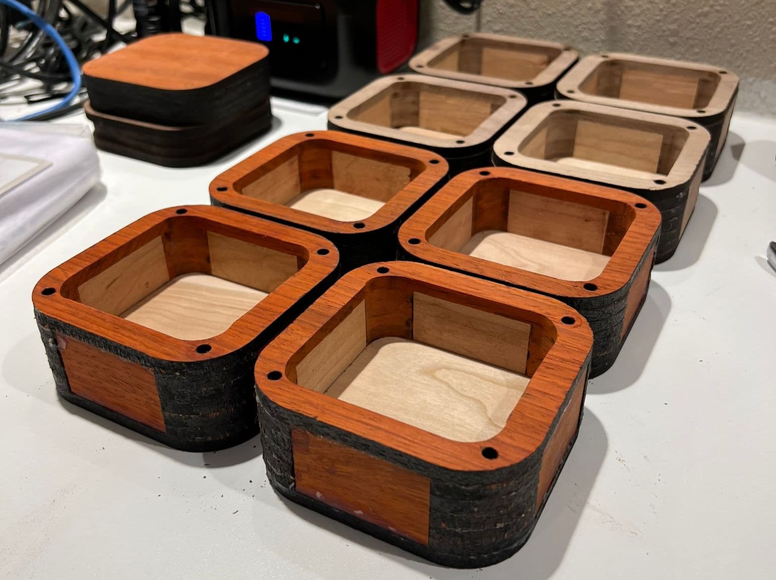
After struggling through routing the box interiors, it was time to glue on the box bottoms. This went as smoothly as before.
Outside Routing
I hesitated before routing the outside of the boxes. Any error here would be highly visible, and the “cut too little” problem on the inside routing would become a “cut too much” problem on the outside, which is not possible to recover from.
A Problem Solved
Fortunately I inadvertently stumbled onto the real cause of the issue. To find a good starting position for the “route the outside” version of the program, I was manually moving the machine around. It was moving too fast, so I made the jog speed slower, but accidentally made it VERY slow. And when I jogged, one axis didn’t move at all.
That should not be possible. Even at an extremely low speed, the machine should make a “click” noise every second or so as it moves a single step, and the movement should happen. But for my machine, under a certain velocity threshold, I was getting no movement whatsoever.
I discovered someone had encountered a similar issue on the LinuxCNC forums. The advice was to make the step timings more conservative. When I opened the config file I had written in 2012, I discovered mine were fairly aggressive:
DIRSETUP = 2000
DIRHOLD = 2000
STEPLEN = 1500
STEPSPACE = 2500
I had set these up based on timings from the G540 manual and had not noticed any issues at the time, but perhaps now for some reason it wasn’t working. I switched to the following settings instead:
DIRSETUP = 2000
DIRHOLD = 2000
STEPLEN = 5000
STEPSPACE = 5000
After this change, the so-called “backlash” problem completely disappeared! I was able to repeatably move with no drift and throw away the backlash compensation in my python script.
Another Problem Solved
I tried one time, on the “test” box, to route the outside with my 2-for-$15 router bit, with terrible results as it tore off an entire corner. I decided to throw those bits in the trash and with my now-exact positioning just do two passes with the downcut spiral bit, flipping the box over between passes. Here’s a view of the torn-off corner of the test box and the new bit about to be used.

Smooth-ish Sailing
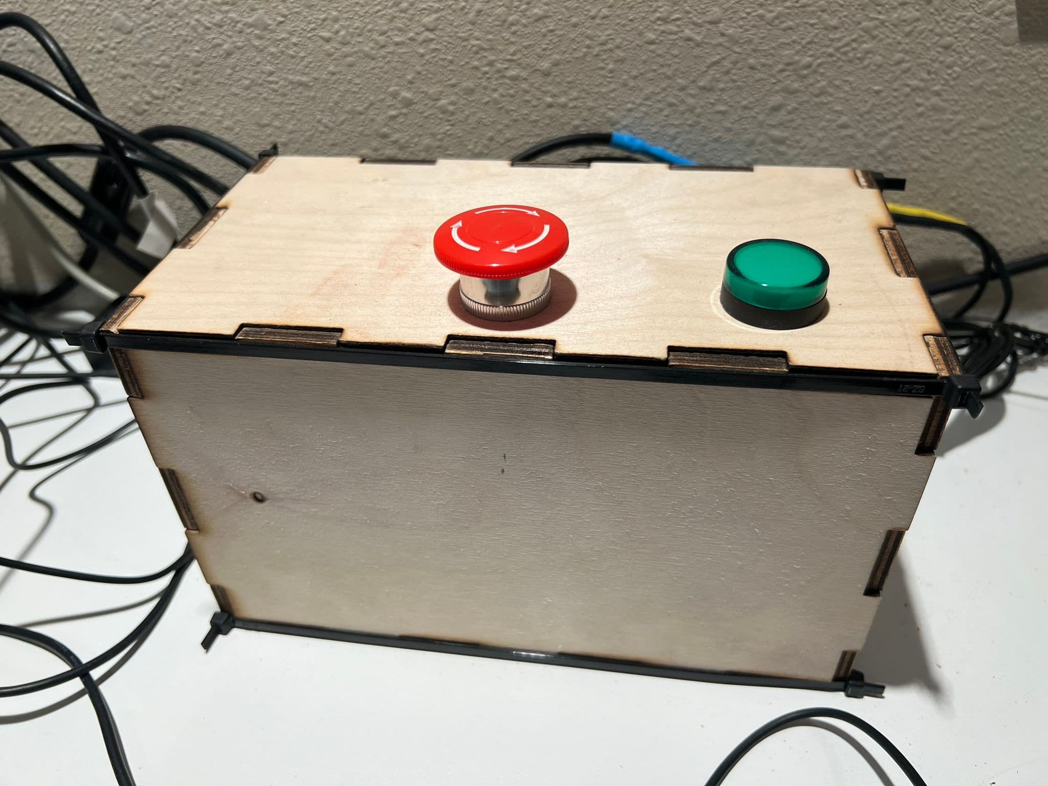
With the problems solved, the routing of the exteriors went smoothly and mostly uneventfully, except for my old non-upgradeable LinuxCNC setup crashing a couple of times and once when I manually typed the wrong “return to home” G-Code after a crash and ran the stopped router bit at full power into the mounted box. This could have been Very Bad but fortunately as the aluminum frame flexed and the motors made weird noises I slammed my hand onto the emergency stop button and nothing actually broke.
Observe the Precision!
Here’s a clip of the router running around the outside of the test box at offset 0.5 mm. You can see at this setting, it follows the corner exactly and shaves off only a tiny amount. I used 1.5 mm for the final pass. Also note here I’m using bolts with actual heads again since without the backlash issue I was confident the router bit wouldn’t run into them.
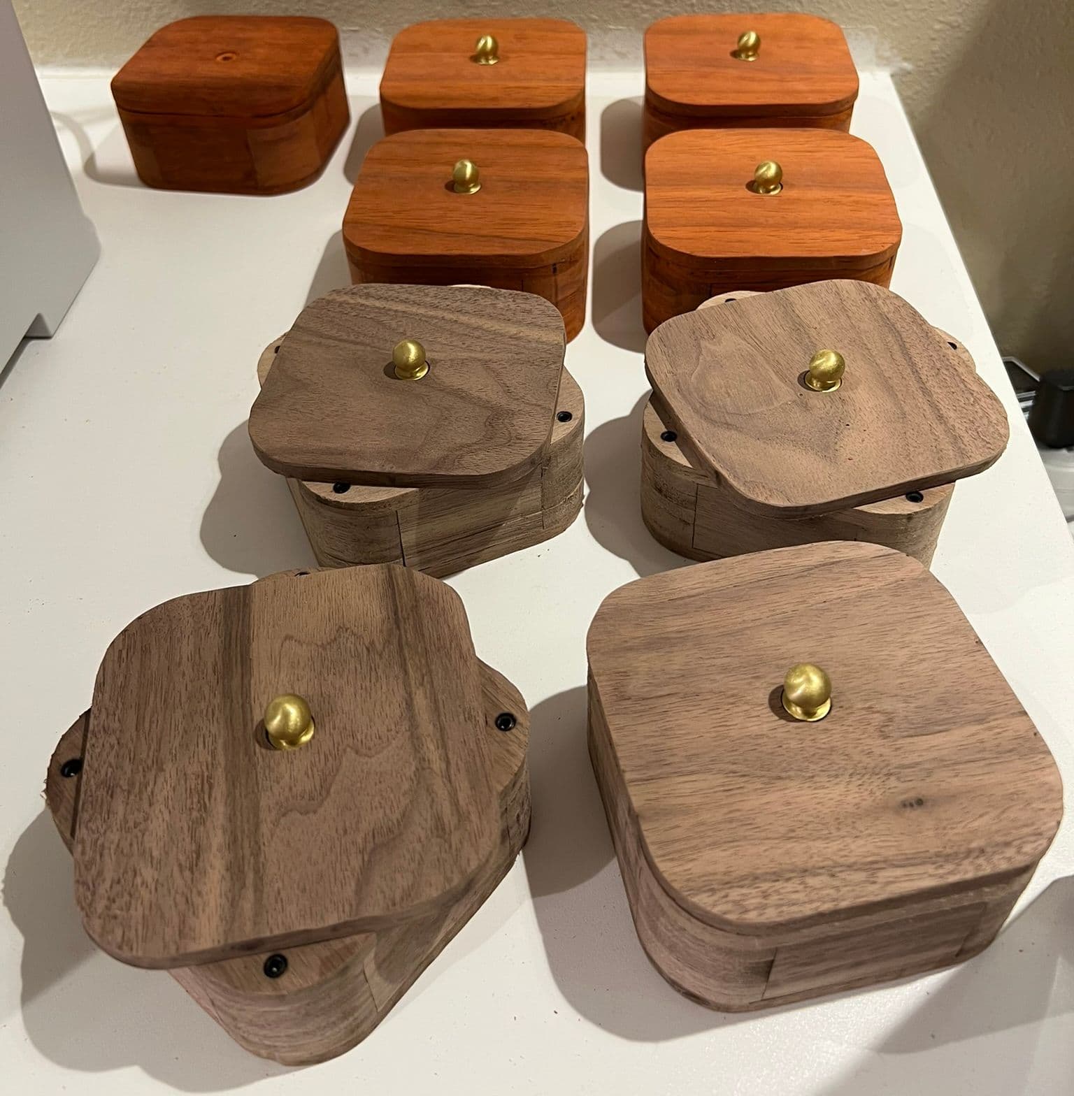
After the boxes were routed, I put the lids on and used a multi-tool to clean them up and make the lid flush with the box sides. Here are all the boxes ready for engraving.
Engraving
I put all of the boxes in the Glowforge and engraved a message on the bottom. Both the padauk and walnut engraved nicely.
Finishing
I decided to finish the boxes in tung oil thinned with d-limonene. This was easy and forgiving but took a lot of time. I tried to reduce the time between coats by heating up my workshop to an uncomfortably warm temperature, using a fan, and aiming infrared lights. This seemed to work and I did two coats at 50% and 70% tung oil the first day 45 minutes apart and one at 95% tung oil the second day.
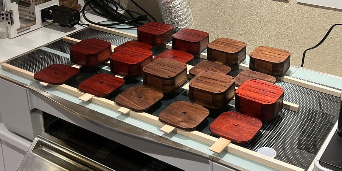
While this looks very nice and it was a “natural” option, I only finished this five days before I gave them as gifts, so had to wrap the boxes with a paper towel around them in case any oil still surfaced (the only problem area was near the engraving where the letters acted as reservoirs).
Would I Do It Again?
I think using the laser cutter with the router is a winning combination, as is tung-oil finishing. I’ll definitely be trying this again, just not any time soon as I am still recovering from the late nights spent getting these done at the last minute. Hopefully something I’ve shared will be useful to your own projects as well! Since this is the part I am happiest with, here’s one more corner view.
